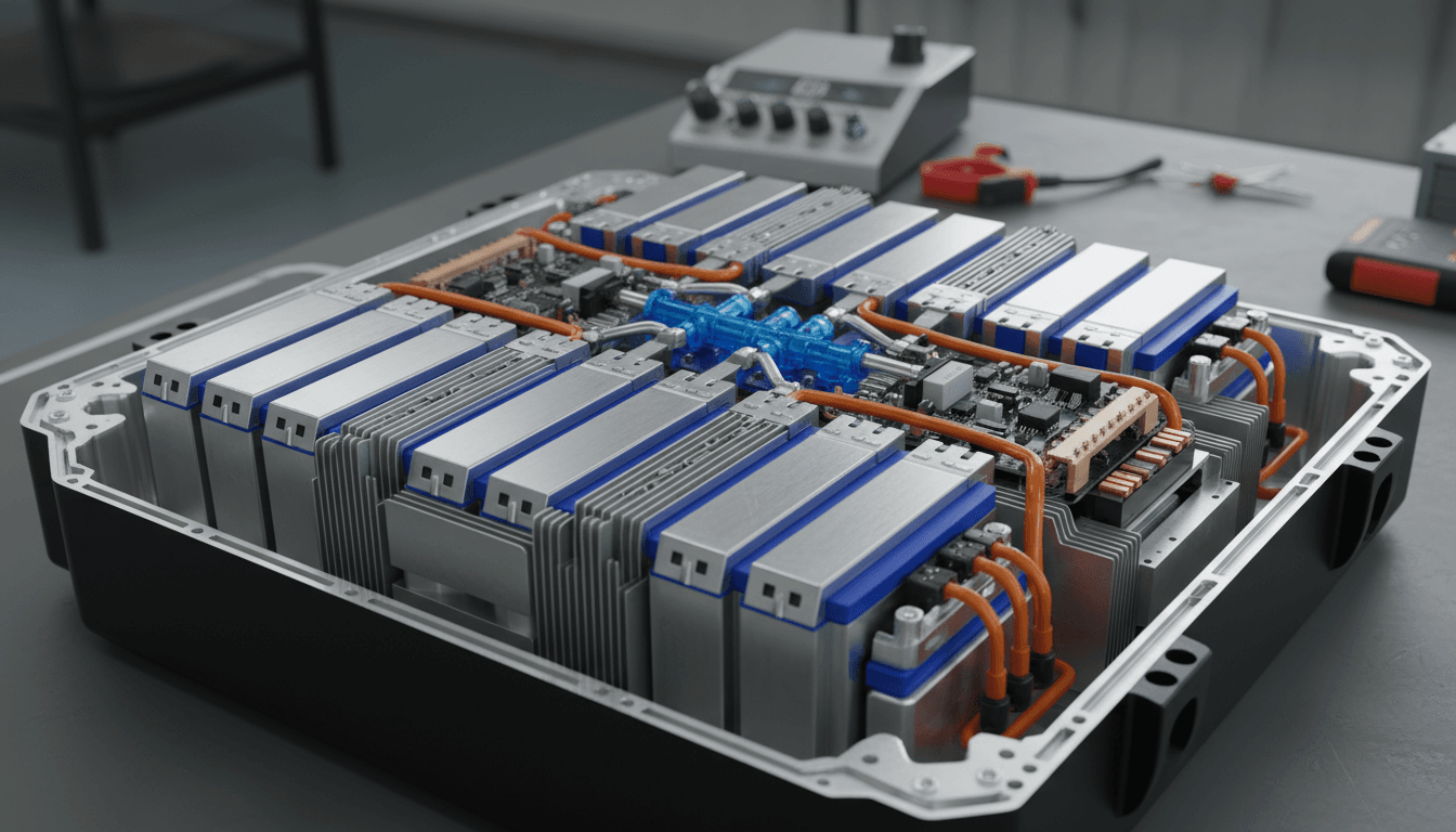
Cell balancing is a fundamental requirement in series-connected lithium battery packs. Manufacturing tolerances, aging characteristics, and self-discharge rate variations cause individual cells to diverge in state of charge over time. Without equalization, the weakest cell limits pack capacity, the strongest cell faces overcharge stress, and the pack degrades faster than its individual cells would suggest [1]. The engineering question is not whether to balance, but how.
Two topologies dominate the literature and the market: passive (dissipative) balancing and active (redistributive) balancing. Passive balancing removes excess energy from higher-voltage cells through resistors. Active balancing transfers energy from higher-voltage cells to lower-voltage cells through switched inductors, capacitors, or transformer-coupled circuits [2]. The academic literature tends to favor active balancing for its superior energy efficiency. Production BMS design, however, must weigh factors that efficiency analysis alone does not capture: functional safety classification, failure mode severity, qualification effort, manufacturing cost, and field reliability across thousands of operating hours.
This application note presents a systematic comparison of both approaches and examines why passive balancing remains the preferred topology in production battery management systems when evaluated through the lens of functional safety and risk analysis.
Operating Principles
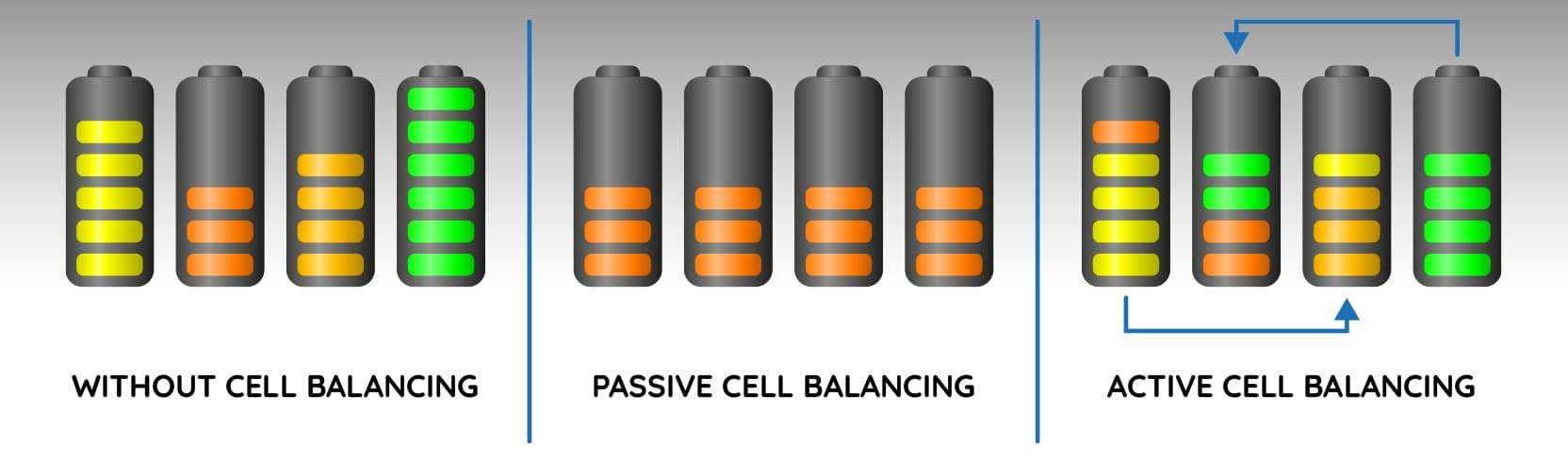
Passive balancing operates during the constant-voltage phase of charging. The BMS activates a bypass path (typically a MOSFET switch in series with a power resistor) across each cell whose voltage exceeds a configurable threshold. Excess charge is dissipated as heat until the cell voltage converges with the pack average. The control algorithm requires only voltage measurement and threshold comparison, with no complex timing or current regulation [3].
Active balancing transfers charge from higher-voltage cells to lower-voltage cells using energy storage intermediaries. Common topologies include switched capacitor (flying capacitor), switched inductor (buck-boost), and transformer-based (flyback or forward converter) circuits. Energy is conserved rather than dissipated. However, each topology requires multiple power switches (MOSFETs), energy storage elements (inductors or capacitors), gate driver circuits, current sensing, and sophisticated control firmware with precise timing requirements [4].
Comparative Analysis
The following table summarizes the key engineering trade-offs between passive and active balancing across parameters relevant to production BMS design.
| Parameter | Passive (Dissipative) | Active (Redistributive) |
|---|---|---|
| Operating principle | Bleeds excess energy through resistors as heat | Transfers charge between cells via inductors, capacitors, or transformers |
| Energy efficiency | Low (energy dissipated as heat) | High (70 to 90 percent energy recovery, topology-dependent) |
| Component count per channel | 1 resistor + 1 MOSFET | 2 to 6 MOSFETs + inductor or capacitor + gate drivers + current sense |
| Typical cost per channel | $0.10 to $0.30 | $1.50 to $6.00 |
| Control algorithm complexity | Low (voltage threshold comparison) | High (PWM timing, current regulation, multi-cell coordination) |
| Failure mode severity | Low: degraded equalization, detectable by voltage monitoring | High: potential cell overcharge, overcurrent, or thermal event |
| Number of distinct failure modes | 2 to 3 (open resistor, stuck MOSFET) | 8 to 12 (inductor saturation, MOSFET latch-up, timing faults, current faults) |
| Functional safety impact (ISO 26262) | Lower ASIL classification: failures degrade performance only | Higher ASIL classification: failures can directly cause hazardous conditions |
| Thermal management | Localized, predictable heat dissipation (PCB design addressable) | Lower balancing heat, but switching noise, EMI, and inductor losses |
| Production qualification effort | Weeks (simple circuit, few failure modes, straightforward FMEA) | Months (complex circuit, extensive FMEA, EMC testing, timing validation) |
| Field reliability (MTBF) | Very high (few components, low electrical stress) | Lower (more components, higher stress on switching elements) |
| Balancing during discharge | Not typically performed | Possible (topology-dependent) |
| PCB area per channel | Minimal (1 resistor + 1 small MOSFET) | Significant (inductor footprint, additional components) |
Functional Safety Analysis
Under ISO 26262, every electronic function in a vehicle must be classified by Automotive Safety Integrity Level (ASIL) based on severity, exposure, and controllability of potential failures [5]. For industrial applications, the equivalent framework is IEC 61508 with Safety Integrity Levels (SIL) [6]. In both frameworks, the severity of failure modes drives the required level of design rigor, verification, and validation.
Passive balancing failure modes are inherently benign. A stuck-on bleed MOSFET causes gradual over-discharge of a single cell, which the BMS voltage monitoring subsystem detects within one measurement cycle. An open resistor or open MOSFET results in no balancing on that channel, a performance degradation that does not create an immediate safety hazard. In ISO 26262 terms, these failure modes typically classify as S0 (no injury) or S1 (light injury, low probability), resulting in ASIL A or QM classification for the balancing subsystem.
Active balancing failure modes can be directly hazardous. A MOSFET stuck in the on-state during charge transfer can force unregulated current into a cell, causing overcharge beyond the cell's voltage limit. A control timing error can direct charge to the wrong cell. Inductor saturation under fault conditions can produce current spikes exceeding component ratings. These failure modes can initiate cell venting or thermal runaway, classifying as S2 or S3 severity (serious to life-threatening injury), which drives ASIL B or ASIL C classification and requires substantially more extensive safety analysis, redundant monitoring circuits, and validation testing [7].
The practical consequence is measurable: qualifying an active balancing system for automotive or certified industrial applications typically requires two to four times the engineering effort and testing duration compared to passive balancing, with corresponding cost implications.
Risk Assessment: FMEA Perspective
A Failure Mode and Effects Analysis (FMEA) for each topology reveals a fundamental asymmetry in risk profiles [8].
For passive balancing, the dominant failure modes (open circuit, short circuit on the bleed path) result in either loss of balancing on one channel or a slow, detectable energy drain. The BMS continues to function safely in either case. The risk priority number (RPN) for passive balancing failure modes is consistently low because severity, occurrence, and detection ratings are all favorable.
For active balancing, several failure modes can result in direct cell damage: charge transfer to an already-full cell (overcharge), uncontrolled current flow during switching transients (overcurrent), and thermal stress on power switches operating at high duty cycles. Detection of these failure modes requires dedicated monitoring circuitry beyond what the base BMS provides, adding complexity that itself introduces additional failure modes. The RPN for active balancing is consistently higher, driven primarily by the severity rating of potential overcharge scenarios.
Total Lifecycle Energy Analysis
The energy efficiency advantage of active balancing, while real, is often overstated in the context of total battery lifecycle energy throughput [9].
Consider a representative scenario: a 14-cell LFP pack with 100Ah cells operating at 420mA passive balancing current. A typical balancing event dissipates approximately 0.42A multiplied by 3.65V over roughly 2 hours, equaling approximately 3.1 Wh per cell per event. Assuming balancing occurs on an average of 4 cells per charge cycle over the battery's 4,000-cycle service life, the total energy dissipated by passive balancing across the entire lifecycle is approximately 49.6 kWh.
The total energy throughput of the same pack over 4,000 cycles is approximately 20,440 kWh (14 cells multiplied by 3.65V multiplied by 100Ah multiplied by 4,000 cycles). Passive balancing losses represent approximately 0.24 percent of total energy throughput. The engineering investment required to recover this fraction through active balancing (additional components, complex firmware, extensive safety qualification, increased failure risk) is difficult to justify on purely economic grounds.
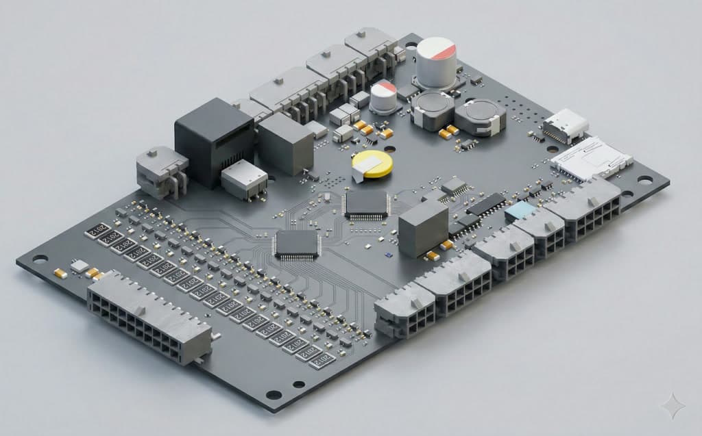
Our Implementation
All LiBat BMS models implement passive balancing as an architectural decision informed by the functional safety and risk analysis presented above [10].
The standard product line provides 420mA balancing current at 4.2V across the BMS1810, BMS1820, BMS1202, BMS1601, and BMS3610 models. For energy storage applications where faster equalization is critical, the BMS1802 slave module delivers 1A balancing current at 4.2V, specifically designed for daily-cycling ESS duty profiles where charge windows may be constrained by solar generation hours or time-of-use tariffs.
Thermal management of balancing circuits is addressed through integrated heat sink provisions on the BMS1802 and independent NTC temperature monitoring on balancing circuits across all models. The firmware implements closed-loop thermal control: balancing current is dynamically throttled if board temperature approaches configurable limits, ensuring sustained operation at the maximum safe rate rather than conservative fixed derating [10].
LiMon, our PC-based configuration and diagnostics tool, provides real-time visibility into per-cell balancing status, configurable balancing thresholds and timing parameters, and continuous data logging for lifecycle analysis [11]. Engineers can observe balancing behavior during development and characterization, while field technicians can verify equalization performance during routine maintenance. The same tool supports every BMS model in the product line, from standalone packs to multi-module high-voltage installations.
Conclusion
When cell balancing topology is evaluated through the combined lens of functional safety classification, failure mode severity, production qualification effort, field reliability, and total lifecycle economics, passive balancing consistently emerges as the more defensible engineering choice for production battery management systems. The energy efficiency advantage of active balancing, while theoretically significant, represents less than 0.25 percent of total lifecycle energy throughput in representative applications. Against this marginal recovery, active balancing introduces failure modes of substantially higher severity, increases ASIL/SIL classification requirements, extends qualification timelines, and raises both unit cost and field maintenance complexity.
For applications where the BMS must meet functional safety standards (ISO 26262 for automotive, IEC 61508/62619 for industrial), passive balancing offers a fundamentally simpler safety case with fewer failure modes, lower severity classifications, and more straightforward verification and validation paths.
References
- [1]Andrea Bonfiglio et al., A Comprehensive Review of Battery Cell Balancing Strategies, IEEE Access, Vol. 11, 2023
- [2]Cao, J. et al., Review of Equalization Strategies for Series-Connected Battery Cells, IEEE Transactions on Power Electronics, Vol. 36, No. 10, 2021
- [3]IEC 62619:2022 — Secondary Lithium Cells and Batteries for Use in Industrial Applications — Safety Requirements
- [4]Diao, W. et al., Active and Passive Battery Balancing Comparison Based on MATLAB Simulation, IEEE PES General Meeting, 2019
- [5]ISO 26262-1:2018 — Road Vehicles — Functional Safety — Part 1: Vocabulary
- [6]IEC 61508:2010 — Functional Safety of Electrical/Electronic/Programmable Electronic Safety-Related Systems
- [7]SAE J2929:2013 — Safety Standard for Electric and Hybrid Vehicle Propulsion Battery Systems Utilizing Lithium-Based Rechargeable Cells
- [8]IEC 60812:2018 — Failure Modes and Effects Analysis (FMEA and FMECA)
- [9]LiBat — Passive Cell Balancing: Why Balancing Current Matters More Than You Think
- [10]LiBat — Battery Management Systems: Complete Product Lineup, Balancing Specifications, and Communication Interfaces
- [11]LiBat — Configuration Tools: LiMon PC Tool, LiMon CONNECT, and LiBat CONNECT Mobile