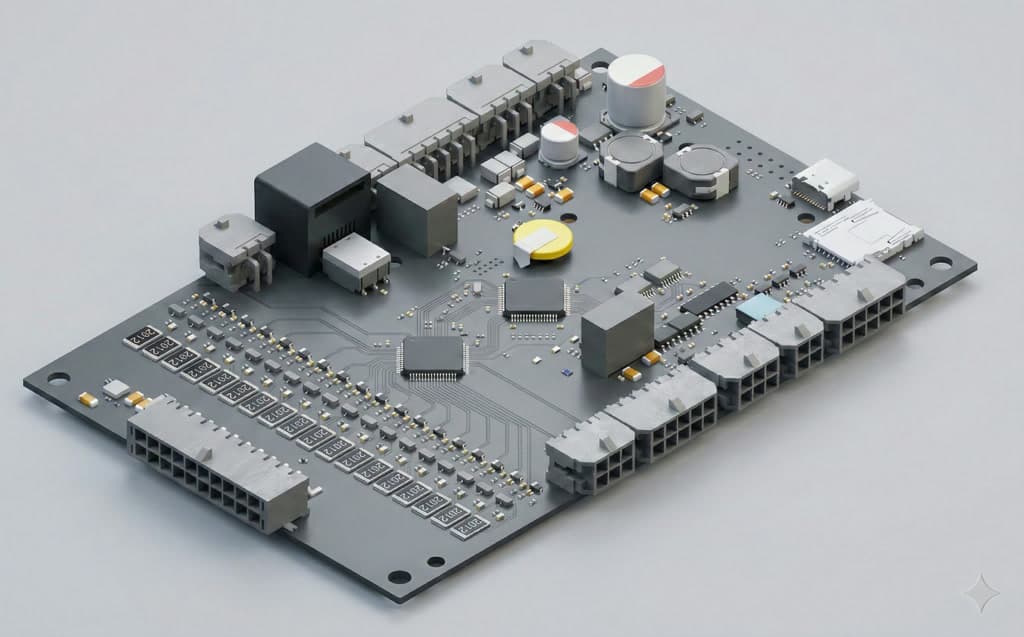

BMS1810
18S BMS MasterA compact battery management system tailored for distributed master-slave battery applications. This fully digital, standalone device is a ready-to-use solution for 5S–18S master battery management systems. It seamlessly adapts to high voltage, high power, and high energy applications through external electrical components like contactors and current sensors. Once configured with the correct system parameters, the BMS1810 operates without ongoing user interaction, ensuring an efficient and hassle-free battery management experience.
Overview
The BMS1810 brings full digital control to demanding 5S to 18S battery packs. It measures every cell with 0.1 mV resolution, balances passively at up to 420 mA, and enforces a complete protection suite out of the box. RS485, RS232, and CAN Bus interfaces keep integration simple, while built-in cloud connectivity and OTA firmware updates support remote fleet management. Configured once, it expands with slave modules to manage up to 120 cells from a single master and then runs without ongoing user interaction.
Highlighted Features
- 01
Flexible Cell Support
Monitors and protects from 5 to 18 cells, depending on cell chemistry.
- 02
Current Limit
Depends on external sensor specification. Any current level can be calibrated, which aligns with 0 to 5V sensor output.
- 03
Current Measurement Mode
Two channel measurement can be set for High and Low current channels, or independent current sensor channels.
- 04
Shutdown or Run Mode
Device runs in full power mode when powered up, but a shutdown mode can be triggered anytime by parameters or user button action. In shutdown mode, all components are powered down, including the input DC-DC, for minimum power consumption.
- 05
Wake-Up
User button input always wakes the device up from shutdown mode.
- 06
Onboard Power Supply
Any power source can be applied as power supply between 18V and 80V. Depending on cell chemistry, the device can directly power up from the battery output.
- 07
Parallel or Series Modes
Standalone master, master-slave, and multi-master modes can be set via the configuration tool for various battery pack architectures.
- 08
Balancing
Balance progress parameters can be set via the configuration tool. Balancing start-stop values, delta values, balancing start status, balance ratio, and the maximum number of balancing cells can be configured for application needs.
- 09
Flexible Inputs and Outputs
Any I/O function can be assigned to any available input or output for maximum flexibility.
- 10
Pre-Charge
Precharge events can be observed and their parameters set via the configuration tool. Precharge can be disabled, or activated in time-only or time/current mode, to meet the maximum flexibility of the battery pack. Any output can be assigned for precharge functionality.
- 11
Display
Any CAN Bus compatible display option can be used for detailed monitoring.
- 12
Remote Monitoring
A GSM and GPS based optional extension board can be used as an add-on. After connecting the extension, a simple firmware upgrade is needed to start remote monitoring of the system via the GSM line.
- 13
Bluetooth and Wireless
You have options for Bluetooth monitoring via a mobile application, or wireless monitoring via a browser on the local network. An external wireless-compatible display option or wireless module device needs to be connected via the CAN Bus line.
- 14
Flexible Digital Charger Integration
Digital charger integration can be configured for various charging scenarios: start-stop charging at a certain level, setting power paths according to the charger connection, preventing driving while charging, and more.
- 15
Charging Curve
Up to 30 charging current points can be defined for a more efficient charging profile suited to any type of battery pack. Current points based on SOC and temperature set the current level when a digital charger is connected to the CAN Bus line.