
BMS1601
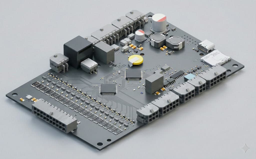
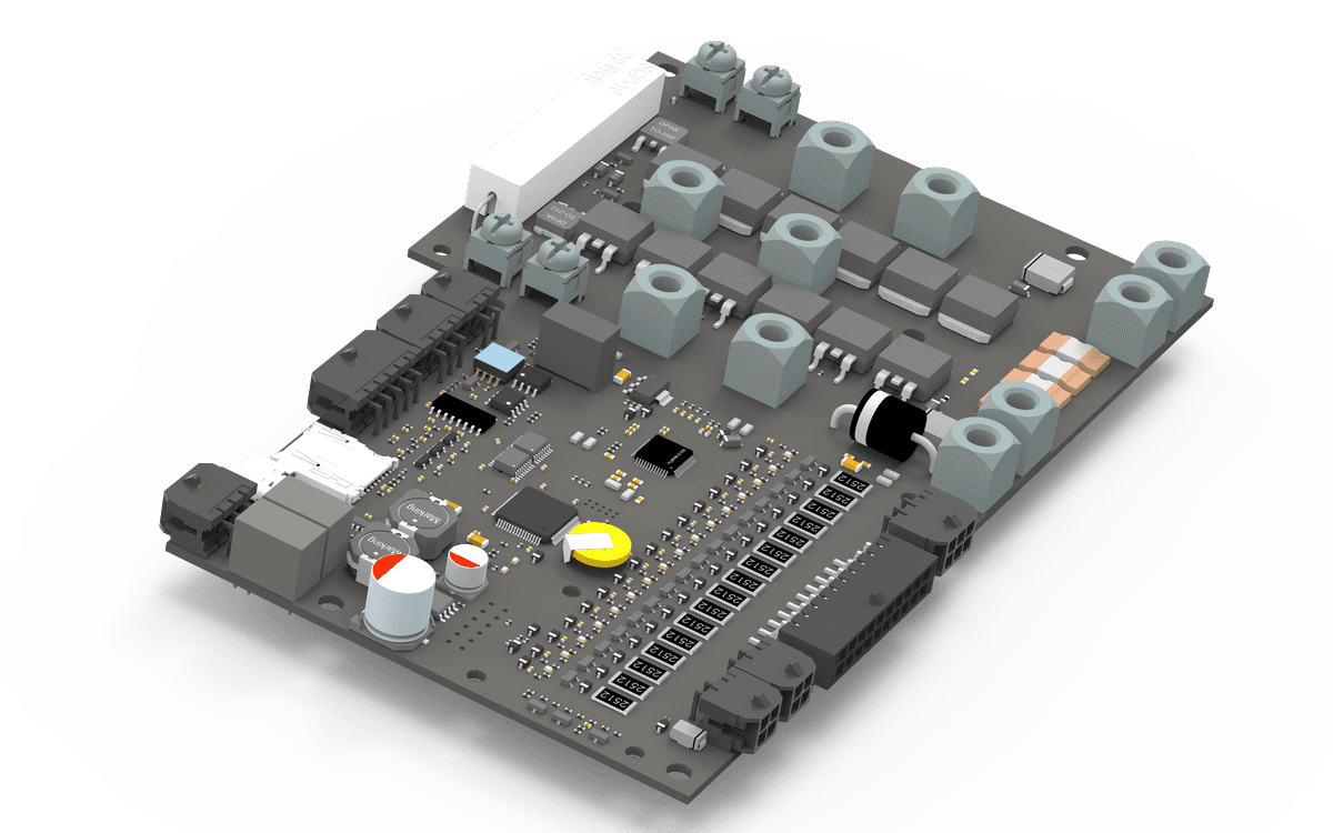
16S Standalone BMSThe BMS1601 is a compact, all-in-one digital battery management system for standalone 6S to 16S lithium applications. It integrates a 250 A power path with onboard MOSFET switching, a 250 A shunt current sensor, and built-in precharge, so it controls charge and discharge directly without external contactors. Four high-side switches, isolated CAN Bus, RS485, and RS232 interfaces, and configurable relays and I/O make it a complete, ready-to-use controller for industrial battery systems.
Overview
The BMS1601 is an all-in-one standalone BMS built for industrial 6S to 16S battery systems. It combines cell monitoring, passive balancing, and protection with an integrated 250 A power path, so onboard MOSFETs switch charge and discharge directly with no external contactors. A 250 A shunt sensor, built-in precharge, and four high-side switches handle the full power stage, while isolated CAN Bus, RS485, and RS232 keep integration simple. Configured once, it runs as a complete, self-contained controller.
Highlighted Features
- 01
Flexible Cell Support
Monitors and protects from 6 to 16 cells, depending on cell chemistry.
- 02
Current Limit
±250A. User need to consider FET cooling options.
- 03
Shutdown or Run Mode
Device runs in full power mode when powered up, but a shutdown mode can be triggered anytime by parameters or user button action. In shutdown mode, all components are powered down, including the input DC-DC, for minimum power consumption.
- 04
Wake-Up
User button input always wakes the device up from shutdown mode.
- 05
Onboard Power Supply
Any power source can be applied as power supply between 18V and 80V. Depending on cell chemistry, the device can directly power up from the battery output.
- 06
Parallel or Series Modes
Standalone master and multi-master modes can be set via the configuration tool for various battery pack architectures.
- 07
Balancing
Balance progress parameters can be set via the configuration tool. Balancing start-stop values, delta values, balancing start status, balance ratio, and the maximum number of balancing cells can be configured for application needs.
- 08
Flexible Inputs and Outputs
Any I/O function can be assigned to any available input or output for maximum flexibility.
- 09
Pre-Charge
On board precharge power path. Precharge events can be observed and their parameters set via the configuration tool. Precharge can be disabled, or activated in time-only or time/current mode, to meet the maximum flexibility of the battery pack.
- 10
Pre-Discharge
On board predischarge power path. Predischarge power path option for limiting input current.
- 11
Display
Any CAN Bus compatible display option can be used for detailed monitoring.
- 12
Remote Monitoring
A GSM and GPS based optional extension board can be used as an add-on. After connecting the extension, a simple firmware upgrade is needed to start remote monitoring of the system via the GSM line.
- 13
Bluetooth and Wireless
You have options for Bluetooth monitoring via a mobile application, or wireless monitoring via a browser on the local network. An external wireless-compatible display option or wireless module device needs to be connected via the CAN Bus line.
- 14
Flexible Digital Charger Integration
Digital charger integration can be configured for various charging scenarios: start-stop charging at a certain level, setting power paths according to the charger connection, preventing driving while charging, and more.
- 15
Charging Curve
Up to 30 charging current points can be defined for a more efficient charging profile suited to any type of battery pack. Current points based on SOC and temperature set the current level when a digital charger is connected to the CAN Bus line.