At 48 volts, a single BMS board can monitor every cell in a pack. The voltage potentials are manageable, the wiring stays reasonable, and one board doing everything keeps the design simple. At 400 volts, that approach breaks down. At 900 volts, it's physically impossible. No single measurement IC can safely span that potential, and routing sense wires across hundreds of volts creates safety hazards that no amount of careful layout can fully mitigate [1].
This is why high-voltage energy storage systems use master-slave BMS architecture: distribute cell measurement across multiple autonomous slave modules, each responsible for a small group of cells, while a master controller aggregates the data and runs system-level logic.
How It Works in Practice
Each slave module sits electrically adjacent to the cells it monitors, typically 5 to 18 cells in series. The slave measures cell voltages using a dedicated analog front-end, reads NTC temperature sensors at thermal hotspots, and runs passive balancing to keep its cells equalized.
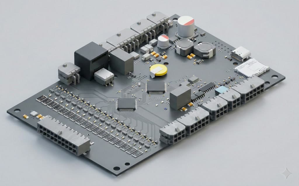
The master controller (in our architecture, the BCU2002) doesn't touch any cells directly. It collects aggregated data from up to 16 slave modules through an isolated communication bus, then handles the system-level work: pack-level SOC and SOH calculation, system protection thresholds, precharge and predischarge sequencing, and external communication to the rack controller or building management system via CAN Bus, RS485 Modbus, or cloud gateway [2].
BMS1802 Slave Specifications: Each slave monitors 5 to 18 series cells with 5 NTC temperature inputs and 1A passive cell balancing at 4.2V. Communication runs through an isolated daisy-chain channel using standard CAT-5 cables. The module accepts 16 to 80 Vdc input supply and is self-powered from its monitored cell string, so no external power routing is needed.
Why Galvanic Isolation Isn't Optional
In a 900V battery stack, the voltage between the bottom cell of the lowest module and the top cell of the highest module is lethal. Standard digital protocols like UART, SPI, and I2C were never designed to bridge that kind of potential. Without galvanic isolation on the communication lines, a single fault could create a current path through the BMS hardware itself [3]. That's not a theoretical concern. We've seen (and been asked to troubleshoot) systems from other vendors where a communication wire fault caused arcing inside the battery enclosure.
The BMS1802 uses isolated daisy-chain lines, connected between modules with standard CAT-5 Ethernet cables. That's a deliberate choice. CAT-5 cables are cheap, available everywhere, easy to route inside enclosures, and their shielded variants handle the electrical noise inside a battery rack well. No custom cabling, no fiber optics, no specialty connectors. We wanted field technicians to be able to source replacement cables from any hardware store.
The isolation architecture also means each slave is electrically referenced only to its own cell string. There's no shared ground between modules, which eliminates the ground loop currents that corrupt measurements and create safety hazards in high-voltage stacks. Each module floats independently, the way it should be [4].
Scaling from Residential to Commercial
The practical value of this architecture is linear scalability. A 48V residential storage system uses a single BMS1810 master monitoring 14 cells directly, with no slaves needed and everything on one board. A 200V commercial installation adds slave modules. A 400V system adds more. A 900V utility-scale deployment chains even more. The same master firmware, the same communication protocol, the same cloud platform, the same LiMon configuration tool [5].
For ESS integrators, this matters because qualifying the BMS for one voltage class effectively qualifies the architecture for all voltage classes it supports. Your test procedures carry over. Your firmware version is the same. A technician trained on a residential unit can service a commercial installation with the same diagnostic tools and the same procedures. We've had customers start with a 48V pilot, move to a 200V commercial product, and then scale to 500kWh-plus deployments, all on the same BMS platform, without re-engineering the battery management layer.
Self-Powered Design: One Less Thing to Wire
A detail that ESS integrators appreciate more than anyone: the BMS1802 draws power directly from the cell string it monitors. Many competing slave designs need an external low-voltage power supply routed to each module. That means additional wiring, additional failure points, and additional installation cost. With self-powered slaves, each module needs only two connections: the cell voltage sense harness and the daisy-chain communication cable. No DC-DC converters, no power supply routing, no extra terminal blocks.
Combined with plug-and-play topology discovery (no DIP switches, no software configuration step), the commissioning process for a full rack goes from hours to minutes. Connect the cell harnesses, plug in the CAT-5 cables, and the system self-discovers its configuration and starts monitoring. We've timed it: a trained technician can commission a 16-module rack in under 30 minutes.
What a 500kWh Deployment Actually Looks Like
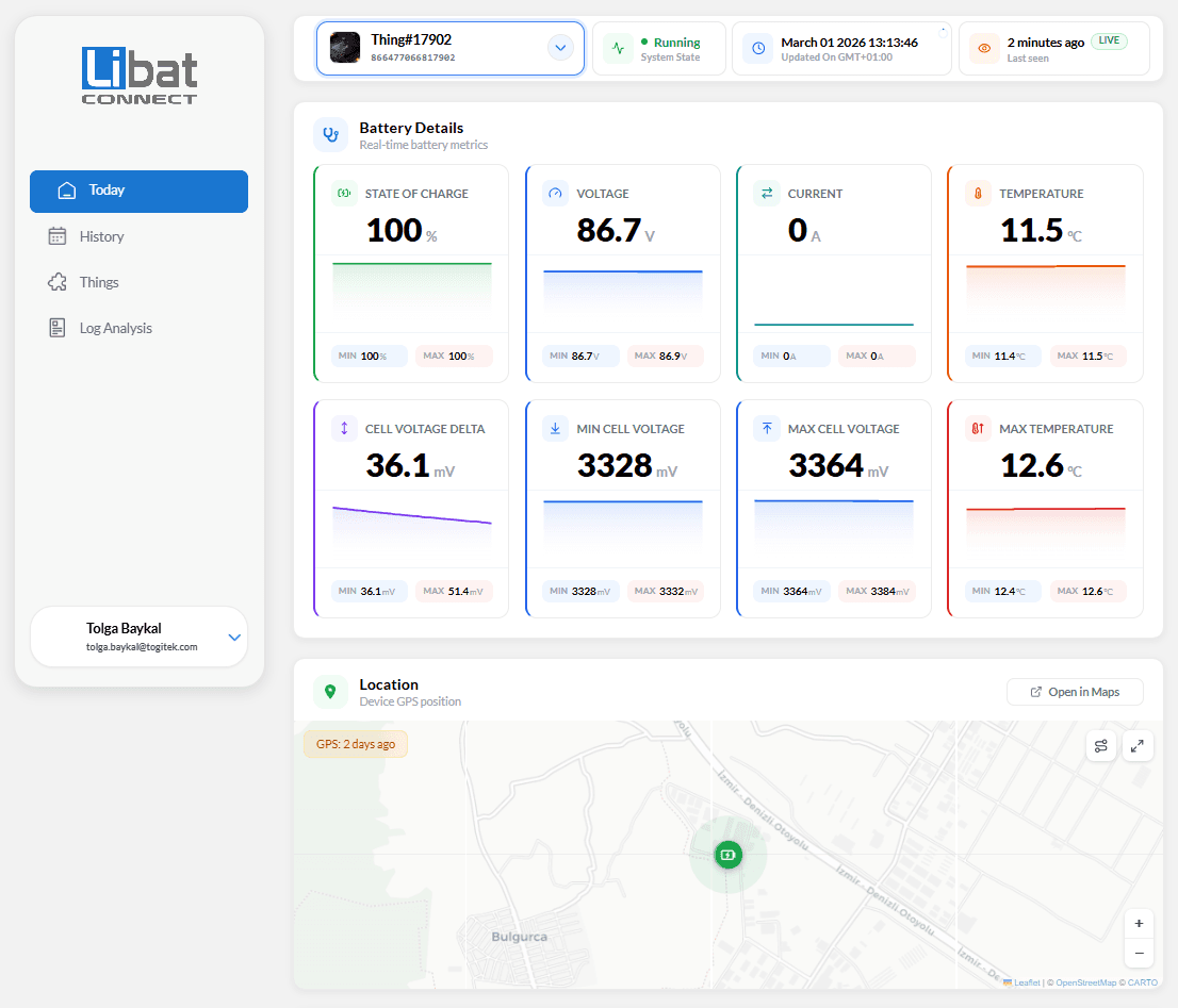
To make this concrete: a 500kWh commercial ESS installation using LFP cells at around 400V [6] typically runs 4 to 6 parallel strings of series-connected battery modules. Each string has 8 to 12 BMS1802 slaves monitoring 14 to 18 cells each, all reporting to a BCU2002 master per string. The masters communicate with the site-level energy management system over CAN Bus or Modbus, and simultaneously stream telemetry to LiBat Connect for remote monitoring and fleet analytics.
Total cell count in a deployment like this: over a thousand individual cells, each monitored with millivolt precision. Commissioning takes a few days for the full battery rack installation, not weeks. Ongoing maintenance is largely driven by cloud-based analytics and anomaly detection rather than fixed-schedule site visits [7].
This scalability, from a single 48V module on a lab bench to a multi-megawatt-hour installation, is what master-slave architecture is built for. Not just managing more cells, but managing them with the same tools, the same firmware, and the same operational procedures at every scale.
References
- [1]IEC 62619:2022 — Secondary lithium cells and batteries for use in industrial applications — Safety requirements
- [2]LiBat — Battery Management Systems: BMS1802 Slave and BCU2002 Master Controller
- [3]IEEE Std 1725-2021 — Standard for Rechargeable Batteries for Multi-Cell Mobile Computing Devices — Isolation and safety requirements
- [4]UL 1973 — Standard for Batteries for Use in Stationary, Vehicle Auxiliary Power and Light Electric Rail Applications
- [5]LiBat — Configuration Tools: LiMon PC Tool, LiMon CONNECT, and LiBat CONNECT Mobile
- [6]BloombergNEF, Energy Storage System Costs Survey 2024 — LFP dominance in stationary storage applications
- [7]IRENA, Electricity Storage and Renewables: Costs and Markets to 2030, October 2017